
12V 0,7A supply using TNY274PN - output is 3V and not rising
Greetings,
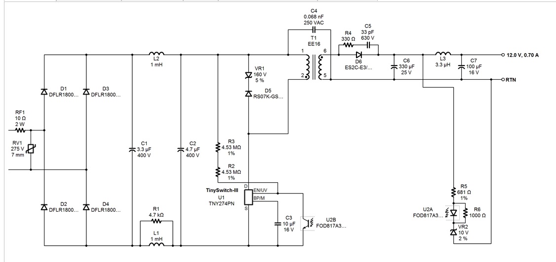
I designed and build a power supply using PI Expert tool for general pourposes. After rebuilding it, i get rid of clicking sound, and now it works, but the output is at constant 3,2V, regardless of Zener diodes that i put into feedback loop. I tried loop as in the schematics, another that worked before in other smps, but its still 3V. I had EXACTLY the same problem when designing another SMPS, but was unable to finish it. I tried to copy feedback loops of factory ready PSUs but without success.
I tried to measure voltage between optocoupler diode terminals. There is 0V at all times. It seems that transformer can't provide enough voltage to rise above Zener voltage and the feedback loop is doing nothing. I followed transformer winding instruction without changes.
All components are brand new. Transformer (ee16 core) was winded (by hand) with PI Expert instructions, and windings are done in right direction, core is also tightly secured. I made in on breadboard for test (I know that's not a good idea, because it may or may not work), but finally it will be soldered properly on PCB. Wiring was checked twice before all was connected to mains.
This is my first SMPS power supply designed from scratch. I made one before, but transformer was made by producer, and it worked both on breadboard and PCB. I'm not totally green in electronics, but I don't have too much experience with SMPS. Please for some help.
Best wishes,
KK
Files
| Attachment | 大小 |
|---|---|
| transformers.jpg | 70.26 KB |
| schematics from PI Expert.jpg | 76.12 KB |
评论
Thank you for your reply.
I made a gap with shims made of thin 0,04mm paper folded to make overall of 0,8mm shims, and put them to form gaps on side legs. PI Expert's estimated gap was 0,154mm. I measured primary inductance of ungapped and gapped transformer. After gaping, it went down forom about 6500uH to 4100uH (PI Expert's nominal primary inductance was 4343uH). I can't make it more precise without disassembling windings.
Then, I used oscilloscope to measure voltages on rectifier anode. Measurement was taken in relation to secondary ground. For most of the time, there was a waveform that looks like sinewave of about 300kHz highest point of 3,6V and lowest of -3,6V. You can look at it in attachment number 1. Sometimes for a brief second, there were some spikes of negative voltage that were quite "big" of -6V and smaller positive of +3,3V - attachment 2. The rectifier diode used was UF4007, so it's a fast diode. Output capacitor is a low ESR type.
The output is still at about 3V, when I used both ungapped and gapped transformer.
I also measured anode voltages of rectifier in another flyback power supply that i built myself with LNK364PN, but design and transformer was built by someone else. Waveform is different, with squareish spikes, quite big negative spikes, and its turned off sometimes completly (from what I know that's the effect of feedback loop).
I'm looking forward to your advice.
KK
| Attachment | 大小 |
|---|---|
| core parameters.jpg | 26.61 KB |
| 1 sine.jpg | 3.22 MB |
| 2 spikes.jpg | 3.37 MB |
I am running a PIXLS file to check the design - what is your required input voltage range?
One more thing - in the "spike" waveform you show, it looks like the duty cycle is very narrow, and the output voltage is being clamped to a very low value. Please check the clamp zener on the primary side and make sure it is installed in the right direction, with anode facing B+.
Thanks for reply.
I want to use Single 230V AC
For primary clamp I used P6KE150A TVS, facing in right direction
My design attached
| Attachment | 大小 |
|---|---|
| 12V07A.uds | 907.5 KB |
Can you show a picture of the drain waveform? Your secondary waveform still looks like the primary is being clamped excessively, which would definitely limit your output voltage.
I'm not sure, my probe (P6100 type) is rated for 300Vpp CATII in 10X mode and I never measured such high voltages with oscilloscope before. Scope is rated for 800Vpp according to user manual. I measured drain voltage with multimeter and it shows about 330V DC (drain do ground). If it is safe, I can do that. It is possible to make high resistance voltage divider between drain and ground and measure its output, then interpolate to actual voltage level?
It's a good idea to just invest in a 100X probe that will have the voltage rating you need. If you are going to work on a regular basis with SMPS, having a 100X probe is a must. If you are not already using a sine wave AC source to power the input of your supply, you will need an isolation transformer so that you can safely probe the primary side of your power supply without damaging your scope probe.
Thanks for your advice, I bought a 100X probe, but it will take some time to arrive. I checked clamp circuit, and found out, that fast diode in it failed. I changed it to UF4007 fast diode. Then, after powering circuit up, output voltage get to 12V but was unstable and rhytmic clicking noise was heard. Then it get to 3V, and with every click it goes to 12V and so on. Then it started to click very fast, and output went to 16V. I saw a faint smoke going from somewhere in the circuit, but strangely there are no burn marks on any of the components. Measurements were taken with multimeter, so they can be not accurate. I tried to power it up after this, and scenario repeats, but there were no overvoltage, there is 12V output when it click, and then falls to 3V. Output capacitor look undamaged, switching circuit also, no suspicious things on transformer, primary and secondary are continous. I searched for schorts that i could accidentaly made but everything is in place. From what I know it may be overcurrent or overvoltage issue. Should I change DP/M decoupling capacitor? I have spare 274s and 275s so I can exchange them if needed.
Congratulations on getting some output from your supply, if intermittent. I have attached a spreadsheet run using PIXLS with the parameters of your current supply. it is attached below as a PDF. The TNY274 is being run at its limits, judging from that the design is mostly running in the continuous mode - a TNY275 may be a better choice for this design. The input bulk capacitance is a little small. This will affect the low line efficiency, as the average B+ voltage will be lower. Two pieces of 4.7uF capacitor would be a better choice.
Anyway, on to your current problems. The supply is likely running in autorestart protection mode. Possible reasons could be a slow diode in the output rectifier position. This diode should be an ultrafast or Schottky rectifier for proper operation. The attached spreadsheet calls out a 60V rated Schottky device, but a 100V rated device would give you a little more leeway in playing with the snubber values to reduce the leakage spike when the output diode recovers in the reverse direction. Since this design is running mostly continuous, there will be a lot of reverse recovery spikes. A Schottky diode would allow more efficient operation than an ultrafast rectifier due to the lower forward voltage drop of the Schottky device.
If you want to do a quick check, you can try subbing in a UF4007 for the output rectifier, since you appear to have those available This should allow the supply to run, albeit at reduced output power, due to the 1A diode rating.
The output rectifier snubber capacitor may be shorted, which would also make the power supply go into protection mode.
Also, make sure that you have the primary inductance that you think you have. If the primary inductance is too small, or if the transformer is running without a gap, the power supply will hit the primary self-protection current limit, in one case due to excessively high primary di/dt, the other case due to transformer saturation.
Also, make sure that the Y capacitor is connected between primary B+ and secondary return. If it is accidentally connected to the hot side of the secondary instead, this could possibly cause the primary overcurrent protection to trip.
| Attachment | 大小 |
|---|---|
| TinySwitch-III Design_Forum_12V_8P4W.pdf | 764.37 KB |
Thanks for reply.
I will rebuild circuit to your specifications and see what will be happening. Besides UF4007 I have also salvaged Shottky diodes in various voltages and amperages so it will try them also. It wouldn't hurt to buy some 100V Shottky's for future designs. Anyway, I will try your advices out.
One more thing - your original schematic shows a 10uF bypass cap for the TinySwitch. This causes the part to revert to reduced current limit mode. To keep standard current limit mode, you will need to change that capacitor to 1uF. For the TNY274 ( the smallest Tiny III) you will need every bit of that standard current limit to deliver the power you need. This is only an issue with the TNY274. Another thing you might want to consider is to change the clamp zener from 150V to 180V. The 150V zener sits rather close to the current reflected voltage of ~133V, and may siphon off energy that by all rights should be going to the output instead.
for general pourposes. After rebuilding it, i get rid of clicking sound, and now it works, but the output is at constant 3,2V, regardless of Zener diodes that i put into feedback loop. I tried loop as in the schematics, another that worked before in other smps, but its still 3V. I had EXACTLY the same problem when designing another SMPS, but was unable to finish it. I tried to copy feedback loops of factory ready PSUs but without success.
I tried to measure voltage between optocoupler diode terminals. There is 0V at all times. It seems that transformer can't provide enough voltage to rise above Zener voltage and the feedback loop is doing nothing. I followed transformer winding instruction without changes.
It would be useful to post a scope picture of both the output voltage and the voltage at the anode of the output rectifier. I would also like to see a picture of the TinySwitch drain waveform, but that will have to wait until you get your 100X probe.
Sorry for delay, I had 24h work shift. My recent steps: added another 4,7uF bulk, changed 10uF to 1uF, added proper snubber for UF4007, changed output low ESR cap (old one was good, so not it's fault), Y capacitor is connected properly. Test load is a 100ohm resistor. I saw that primary inductance should be 2741uH according to PIXLS when gap is 0,23mm, and there are 168 turns on primary. After rebuilding the gap, I have about 3400uH. Its too much. Why there is a divergency between PIXLS and PI Expert? PI Expert's inductance was about 4200uH. I tried changing core type from default to P40, but that changed nothing in transformer construction nor in gaping and primary inductance.
Anyway, there are some different output waveforms. While rectified stays roughly the same (spikes of 15V every "click"), the anode looks "better". There is a square wave every time the circuit clicks, when protection is not tripping, there are only light noises, so I think that IC is not working all the time, but sine from previous waveform is gone. After lowering the inductance, "clicks" have become quieter I think.
From those symptoms I assume that the transformer is saturating, thus overcurrent protection kicks in.
EDIT: IT WORKS! I dropped the inductance with bigger gap to about 3mH on primary, and achieved stable 12V output (with ripple, because i disassembled output filter) with 100ohm load. I'm still wondering why PI Expert and PIXLS show not the same parameters.
| Attachment | 大小 |
|---|---|
| rectified.jpg | 2.52 MB |
| rectifier anode.jpg | 2.54 MB |
From your initial schematic, it appears that PI Expert chose reduced current limit for the TNY274 (the 10uF bypass cap is a giveaway). This would naturally dictate a higher inductance transformer to attain the required output power. With PIXLS, you can manually force the current limit chosen, so I opted for normal current limit, as the TNY274 is being pushed very hard to deliver the required output power. This will of course result in a lower inductance for the transformer.
Thanks for your advices. I think, that from now on I would be able to make another power units by myself.
Many thanks.
KK
Thanks for using TinySwitch in your design.
One essential piece of data missing here is the inductance of your transformer. A flyback transformer needs a gap in order to be capable of storing energy without saturating, This gap can be provided by either grinding the center lag of the ferrite core or using shims in the two side legs. The shimming is customarily done using the same tape used for constructing the transformer.. The effective gap using shims will be twice that of a gap obtained by grinding the transformer center leg, as the magnetic path is interrupted both at the outer and center legs of the core. It is also a good idea in this case to check the polarity at the output rectifier diode anode while the primary switch is on - the voltage should go negative at the output rectifier anode when the primary switch is on..