
Variation in Vce monitoring threshold voltage of 2SC0106T2A1-12 gate driver
Hello,
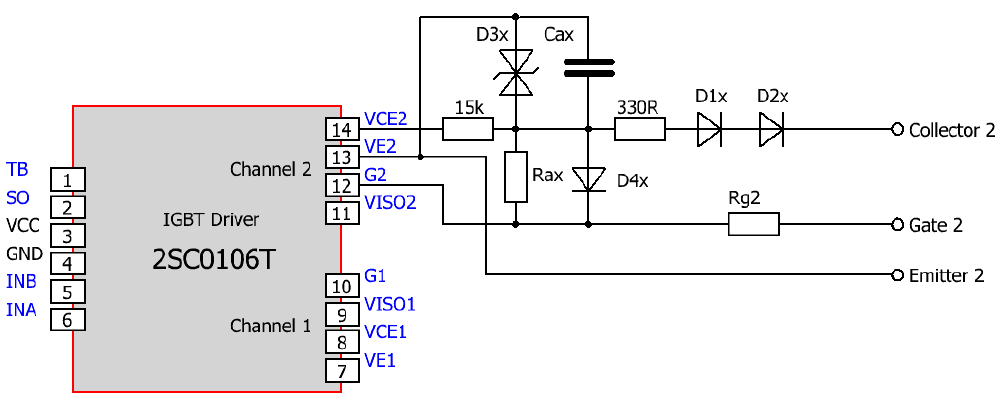
I am trying to test the short-circuit protection feature of the 2SC0106T2A1-12 gate driver. I am using the circuit similar to the one mentioned in the application manual in page # 13 (see attached image). I use an external adjustable power supply connected between "Collector 2" and "Emitter 2" to emulate the Vce voltage of an IGBT.
The Vce monitoring threshold voltage is 9.3 V according to the datasheet. I checked the voltage on this pin (pin #8 or pin #14) while gradually increasing the power supply voltage. I tested 3 gate drive modules and I am getting different voltage for each of them as well as each channels. The trip happens at 9.1 V, 9.2 V, 9.6 V, 9.4 V, 9.6 V, 10 V for the six gate drives on 3 modules. Is such a huge mismatch in the trip levels normal?
I have used Rax = 10 kOhm and Cax = 100 pF
Thank you.
Files
| Attachment | 大小 |
|---|---|
| Circuit diagram | 24.92 KB |
评论
Hi,
The test setup is as follows:
A DC power supply is connected across the “Collector 2” and “Emitter 2” pins to emulate the Vce voltage of an IGBT. The voltage is kept at zero initially.
A digital multimeter is connected between pins VCE2 (pin #14) and VE2 (pin #13) of the gate drive module to measure the voltage at which the gate drive output turns off (tripping) when it detects a short-circuit.
The gate drive output is then enabled by activating the logic input. The voltage measured between “Gate 2” and “Emitter 2” is about 15 V.
Now, the DC power supply voltage is gradually increased. A corresponding increase in the VCE2 (pin #14) voltage is observed on the multimeter. The DC power supply voltage is gradually increased until the gate drive trips.
If I am understanding correctly, according to the datasheet, the VCE2 voltage will be equal to the diodes’ (D1x, D2x) voltage drops + the drop across 330 ohms resistor + Vce voltage of the IGBT (DC power supply voltage). The trip should happen when this voltage reaches 9.3 V.
However, I am observing the trips at random voltages as mentioned in the previous post.
I hope that the explanation is clear now.
Thanks.
Hi
Thanks for the explanation, according to your description it is clear that you understands how the short-circuit function works on PI product in general.
However, your test result shows a bigger range than what we have in our lab. I am not sure how you read the "9.3V" in your test, you actually have two ways, that you freeze the value of the multimeter when Gate Voltage drops or SO feedback happens, depending on how you read the "9.3V", it will always show the slight difference on result. For PI products, we actually test and guarantee this at the ASCI level.
In order to support you to step forward on this question, I would like to understand from you what is your real application problem in your system that let you do this investigation, since according to our experience, the most important parameter for this function is the short-circuit response time, which is the combination of "9.3V", Rax, Cax at least.
Gate Driver Support
Hello,
Thanks for your reply.
The "9.3 V" is the value shown on the digital multimeter just before an LED connected to the SO output turns ON indicating that a fault has happened, while gradually increasing the DC power supply voltage connected across Collector2 and Emitter 2.
I want to protect the devices in a MOSFET based three-phase inverter bridge. There are 4 MOSFETs connected in parallel for each switch which is driven by the gate driver modules. As you might already know, unlike IGBTs, MOSFETs with very low Rds(on) and hence have low ON-state Vds drop. Therefore, I am trying to tune the protection level by adding zener diodes in series with D1x and D2x. In my application, I would like the trip to happen when Vds goes higher than 3.0 V. But because of the mismatch, I am seeing trips happening at voltages different from 3.0 V. Even with the same value of zener diodes, there is a mismatch in the trip levels from the gate drives' channel to channel as well as module to module, way larger than the zener diode tolerance.
Thanks.
Hi
thanks for your explanation,
for your real problem, which problem do you have
a: has false triggering
b: want to have the triggering while the Vds is exactly at 3.0V
Hello,
I would like to see the fault triggering between Vds = 2.9 V and 3.1 V.
Thanks.
Hi
Since the 2SC0106T has the built-in Vce detection threshold level, you really have limited freedom to set a trigger point as you wanted
and our 2SC0108T has the additional REF pin, which allows adjusting the threshold level easier by just one resistor
Hi Matbob
Thanks for approaching us
Is it possible to describe your test method?
This value is not easy to measure.
Gate Driver Support