
TNY286_TL431 design questions
Posted by: xyz
on
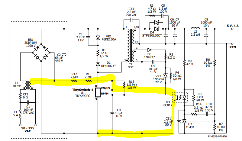
The design of TL431 here is different from the connection method of other manufacturers. I don’t know how to calculate it to ensure that the feedback can operate normally in the worst case.The difference is like pulling the resistor from AC input to opto, Pin1 (EN/UV) does not write Vdd voltage and the pull-up resistor of the internal IC.
Because I need to calculate the Ic current of the opto to ensure that the If current can be greater than the Ic current after the CTR decays.
Files
| Attachment | 大小 |
|---|---|
| TNY286.PNG | 83.4 KB |
Hi xyz,
The difference in connecting the EN/UV circuit to one of the AC line input compared to the regulated DC input is that the voltage on R12 to S pin will oscillate from 0 to the DC input voltage instead of being near constant DC. This change is mainly to improve no load input power consumption. Another difference is that during an output overvoltage event, latch-off will occur and will reset every half-cycle (~8.33 ms for 60 Hz AC) instead of remaining latched until AC recycle is done. The calculation for the maximum optocoupler Ic current should not be any different compared to when R12 is instead connected to C2.
You can refer to the document of RDR-295 for the schematic you attached and look into sections 4.4, 4.5 and 4.6 for a more detailed explanation on how the optocoupler circuit and EV/UV pin circuit works. You can also look into AN-82 which is the design guide for power supplies using TinySwitch-4 families. Thank you for using PI Forum.